2022年12月14日星期三

The Electric Arc Furnace Graphite Electrode Production Process

Electric Arc Furnace Graphite Electrode


The Electric Arc Furnace Graphite Electrode Production Process

The Graphite Electrode Production Process Includes the Following Steps:

1- Shredding and mixing 2- Primary shaping 3- Primary curing 4- Impregnating 5- Secondary curing and graphitizing 6- Machining

1- Grinding and mixing: metallurgical coke or petroleum coke grains are crushed in a stone crusher to a very small extent (unspecified size), after this step, it is mixed with a coal bituminous liquid and pitch (pitch) and a special resin. are mixed to form a paste. The composition of this mixture and the size of the graphite grains are very important and have a direct relationship with the electrical resistance of graphite.

2- After the stage, a paste is injected into metal molds for forming, and then they are vibrated at the same time and at a high speed for compression.

3- In the initial cooking stage, the graphite rods are transferred into an autoclave so that the injected liquid evaporates and the so-called electrode dries. In this step, the electrodes are dried vertically along with the mold.

4- According to the definition, in the impregnating process, a liquid containing antioxidants, which is prepared with nanotechnology, is injected into the electrode to oxidize the electrode under the strong influence of the highly oxidized substance, ozone. This material is formed under the influence of the electric arc and from the proximity of the oxygens in the electric field resulting from the arc.

5- At this stage, the secondary baking of the electrodes with a gentle thermal gradient started to heat up to 3000 degrees Celsius in resistance furnaces with a neutral atmosphere and without the presence of oxygen and other oxidizing gases until gradually these cokes of the raw material, which in terms of Amorphous structures are transformed into graphite with a hexagonal layered structure. This process is time-consuming and long.

6- After the baking and cooling stage, the electrodes are sent for machining. In this process, the end of each electrode is machined and threaded. In this place, parts called nipples or brains are closed, and the electrodes are connected to each other in series.

The primary material for making needle electrodes is a coke and its production is only monopolized by a few companies. Its production method is based on baking and annealing metallurgical coke or petroleum coke with a gentle thermal gradient. According to some producers, this process takes a lot of time to turn metallurgical coke or petroleum coke suitable for production into graphite electrodes.


Hani Tech is the one-stop supplier able to design, manufacture, install and commission your melt shop and hot rolling mill plant from A to Z.


EAF Steelmaking


Electric Arc Furnace Graphite Electrode


2022年12月9日星期五

Electric Arc Steelmaking Furnace

Electric Arc Steelmaking Furnace


Electric Arc Steelmaking Furnace

Electric arc steelmaking furnace - a furnace in which the heat of an electric arc is used to melt steel. The capacity of arc furnaces ranges from 6 to 200 tons. These furnaces serve primarily for the smelting of alloyed and high-quality steels, which are difficult to obtain in converters and open-hearth furnaces. One of the main features of an arc furnace is the ability to achieve high temperatures in the working space (up to 2500 °C).
 
Main Advantages of Electric Arc Steelmaking Furnace:
 
  1. The ability to control the redox properties of the medium during melting, as well as to provide a reducing atmosphere and non-oxidizing slags in the furnace, which predetermines a small waste of alloying elements (for reference: waste is metal loss as a result of oxidation during melting or heating);
  2. Rapid heating of the metal is associated with the input of thermal power in the metal itself. This allows large amounts of alloying elements to be introduced into the furnace;
  3. Smooth and precise adjustment of steel temperature;
  4. More complete than in other furnaces, metal deoxidation, obtaining it with a low content of non-metallic inclusions;
  5. obtaining steel with low sulfur content.
 
One of the disadvantages of an electric arc steelmaking furnace is the need to ensure high quality of charge materials, of which 75-100% is steel scrap. Scrap should have as little as possible impurities of non-ferrous metals, phosphorus, and rust. Scrap must be heavy to load in one go, because. each load of scrap significantly lengthens the melt. Another disadvantage of the arc furnace is the unproductive use of the furnace capacity during periods of low energy consumption (oxidation and reduction periods).
 
Arc furnaces are divided into direct-operated furnaces (the arc between the electrode and the heated material), indirect-operated (the arc between the electrodes outside the heated material), and closed-operated (the arc is under the material layer). An example of a closed-action furnace is a ferroalloy furnace. In furnaces of this type, the lowest heat loss through the roof, because. it is shielded from the arc by a layer of material.
 
Steel arc furnaces are usually direct-acting furnaces and are divided into AC furnaces (ACF) and DC furnaces (DCF). In alternating current furnaces, a three-phase current passes between the electrodes through an intermediary, which is the charge (metal, carbon). These furnaces require expensive devices to compensate for low cos ϕ and there are large inductive resistances of the current supply in a short network, which causes spontaneous power transfer from one phase to another. As a result, the formation of a "dead" (lack of power) and a "wild" (excessive power release) phase is possible.
 
In DC furnaces, power is released evenly and there are no compensating devices inherent in AC furnaces. Instead of three graphite electrodes, there is only one in the DPPT (although it can be split into several), and the second electrode (anode) is the bottom electrode. The advantages of DC furnaces compared to AC furnaces are 1.5-2 times less consumption of graphite electrodes, 5-15% less power consumption, 10% less wear of refractories, 8 times less dust emission (0.9- 1 kg/t instead of 7-8 kg/t in an AC furnace) and in a lower noise level (90 decibels instead of 120 decibels in AC furnaces).
 
The main disadvantage of DC electric arc steelmaking furnaces is associated with obtaining direct current from alternating current and high capital costs for current converters. To compensate for this shortcoming, special semiconductor technologies have been developed. The disadvantages of DBPT also include the need to use more expensive electrodes of a larger diameter (700-750 mm) instead of electrodes with a diameter of 350-610 mm in the EAF and the insufficient reliability of the bottom electrodes.
 
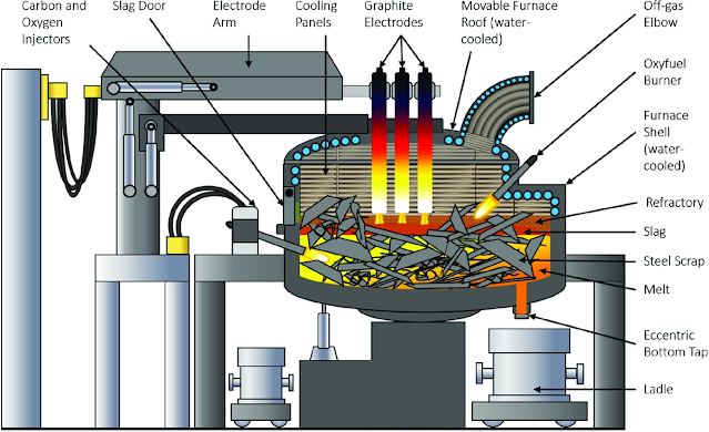
The principle of operation of the chipboard is as follows. Charge materials are loaded onto the hearth of the furnace from above into the openable working space using a tub (basket) with an opening bottom.
 
After that, the roof of the furnace moves onto the bath, which has the shape of a bowl. The electrodes are lowered through the holes of the arch until a short circuit occurs with the charge and electric arcs are ignited. Melting and heating are carried out due to the heat of electric arcs that occur between the electrodes through liquid metal or metal charges. After melting the charge in the furnace, a layer of liquid metal and slag is formed. By adding deoxidizers and alloying additives to liquid steel, the desired steel composition is achieved. Finished steel and slag are discharged through a drain chute by tilting the working space. The working window, closed by a damper, is designed to control the progress of melting, repair the hearth, load materials, and intermediate slag discharge (during the oxidation period). The temperature of liquid steel during tapping is 120-150 °C higher than the liquidus temperature and is 1550-1650 °C.
 
In the process of melting, 4 periods are distinguished:
 
1 - preparation of the furnace for melting (20-40 minutes). Correction of worn areas under filling the hearth with magnesite powder, filling the charge;
 
2 - melting period (70-180 minutes). The input of the maximum electric power. Heating and melting of the charge; slag formation due to the oxidation of silicon, manganese, carbon, and iron with air oxygen, scale. It is possible to use oxy-fuel burners installed in the walls or on the roof to accelerate the melting of the solid charge. It is possible to blow liquid metal with oxygen to accelerate the process of melting the remains of unmelted charge. Removal of the main mass of phosphorus from the metal due to the presence of the main ferrous slag;
3 - oxidation period (30-90 minutes). Draining the bulk of the slag to remove phosphorus from the furnace; additive of slag-forming additives (lime, etc.); ore additive for intensive oxidation of carbon, obtaining the effect of "boiling", during which metal is dephosphorized and hydrogen and nitrogen are removed with CO bubbles; periodic discharge of foamed slag; heating the metal to the outlet temperature; complete draining of the oxidizing slag to prevent the transfer of phosphorus from the slag to the metal during the recovery period;
 
4 - recovery period (40-120 minutes). The additive of ferromanganese and ferrochromium to bring the content of manganese and chromium to the required for the steel grade being smelted, as well as ferrosilicon and aluminum for metal deoxidation (deoxidation is the removal of oxygen from liquid metal by adding deoxidizers: carbon, silicon, manganese); picking up high-basic slag by adding lime, fluorspar, and fireclay to accelerate deoxidation and removal of sulfur from the metal; deoxidation with ground coke; deoxidation with ground ferrosilicon mixed with lime, fluorspar, and coke; if necessary, the addition of strong deoxidizers: Silico calcium and aluminum; alloying of steel with ferrotungsten, ferrovanadium, ferrosilicon, ferrotitanium, aluminum, etc.; release of steel together with slag for additional conversion of sulfur and non-metallic inclusions into slag.
 
 
The main parameters that limit the melting process are the lining temperature and the total electric power. If the temperature is low, then the power is maintained at maximum without the danger of overheating the lining. Temperature exceeding 1500-1800 °C is undesirable for lining. The hearth is usually made of magnesite bricks, and the walls and vault of the bath are made of magnesite-chromite bricks. The resistance of the lining of the walls and the vault ranges from 75-250 melts. The resistance of the hearth is 1500-5000 melts, provided that it is renewed after each melt by filling with magnesite powder. The total thickness of the hearth on furnaces operating with electromagnetic stirring should not exceed 800-900 mm.
 
During melting, a large number of dusty gases are released from the chipboard (especially during the oxidation period). The temperature of the gases is 900-1400 °C. The average amount of gases during the oxidation period reaches 180-200 m3/(t⋅h). In wet dusting, the gas is cooled and then released into the atmosphere.
 
To reduce energy consumption in chipboard, the following is recommended:
 
1. Transfer of oxidation and reduction operations to an arc furnace of lower power (“ladle-furnace” installations. In this case, the idle power is sharply reduced, and, accordingly, the specific energy consumption drops;
2. Preliminary fuel heating of the mixture before loading into the EAF ( electric arc steelmaking furnace). You can use a loading bucket for this. Result: saving expensive electricity;
3. Use of gas-oxygen burners for preheating and melting the charge. Result: reduction in melting time and energy consumption (by 10-15%). The same effect is obtained when carbon-containing materials are blown in an oxygen jet;
4. Use of physical heat of exhaust gases with the use of dry purification for subsequent heating of water or without purification for heating the charge;
5. The use of physical heat of liquid slags for obtaining hot water and other purposes;
6. Inclined installation of electrodes (up to 45 degrees from the vertical), which allows gases to be removed vertically upward through the shaft and to heat the charge. Additional effect: reduced consumption of electrodes due to cooling of their ends.
 
Arrangement of the Hearth, Walls, and Arch of the Main Electric Arc Steelmaking Furnace
 
The hearth of an arc furnace, as a rule, withstands a two-year campaign (more than 4,000 melts) until it is completely replaced during the next major overhaul.
 
The mainlining of the hearth of an arc furnace consists of a ramming layer, a brickwork layer, and a heat-insulating layer. When creating it, the following sequence of operations is observed:
 
The bottom of the metal casing of the furnace is laid out with sheet asbestos 10-20 mm thick, overlapping the seams between themselves.
 
Fireclay powder is poured to level the surface (5-30 mm). The walls of the casing are insulated with sheet asbestos in one or two rows. Fireclay bricks are laid on the leveled surface of the bottom in one or two rows on a die and on an edge, filling the seams with fireclay powder and tapping them with a wooden hammer.
 
Magnesite bricks are laid out on the fireclay on the edge, on the die in linear rows, and the masonry is carried out from the center of the bottom of the furnace to the walls. The seams of parallel rows of masonry should not coincide, therefore, in each row, the bricks are laid out at an angle of 45 ° to the previous row. The masonry is done "dry", by rubbing the bricks together. The thickness of the seams should not exceed 1 and 2 mm, respectively, in the center and at the walls (control with a probe).
 
Before laying the hearths, bricks of the same size are selected without chipping. Each row of masonry is sprinkled with magnesite powder, tapping the bricks with wooden hammers for compaction. A temperature gap up to 65 mm wide is left around the circumference of the furnace casing, filling it with asbestos wool. Distortions in the width and verticality of the gap are not allowed.
 
The laying of slopes from normal magnesite bricks is led by ledges. On the masonry of the hearth, a circle of a certain diameter is outlined (depending on the capacity of the electric arc steelmaking furnace) and an edging ring of magnesite brick is laid out along it. The space between the ring and the hearth is leveled with a rammed magnesite mass, and the first row of slopes is laid out on the formed platform. Subsequent rows of laying slopes are carried out with overlapping of the seams of the previous row, forming ledges that provide a given width of the future upper row. The rammed mass is tamped into the temperature gap of the slopes, overlapping it with the upper row of brickwork. After leveling the top of the slopes with magnesite powder, they begin laying the walls.
 
During the laying of the walls, their thickness is reduced (towards the arch) and the walls are given a slight slope (15-20 °).
 
To reduce heat losses through the walls, the masonry is isolated from the frame with the asbestos sheet, foam fireclay or fireclay bricks, and other materials. For convenience in work, sheet asbestos is glued to the frame of the furnace with liquid glass.
 
The walls of the main electric arc furnaces are laid out with magnesite and chromium-magnesite bricks (Dinas brick in the main furnace quickly slags under the action of lime dust, so this wall laying is not very common). In the walls of heavy-duty arc furnaces, instead of refractory masonry in the upper zone, water-cooled elements are used in accordance with certain requirements (element wall thickness 14-20 mm; water consumption for cooling 6-9 m3 per 1 m2 of wall element area; elimination of contact of elements with slag and metal; water flow rate in the elements is 2-6 m/s; spikes on the surface should prevent the refractory lining and ledge from slipping). The use of water-cooled elements (panels) leads to a slight increase in power consumption for melting (up to 10 kWh/t, or up to 2%), a decrease in refractory consumption by 50%, and an increase in the productivity of the arc furnace up to 25%.
 
Sufficiently widespread use was made of masonry walls in spare metal frames. The brick in them fits tightly on refractory mortars or concretes of the appropriate compositions.
 
The laying of the outlet is carried out on mortar or chrome concrete. For laying columns, chromo-magnesite bricks are used, and for arches, periclase-spinel bricks are used. The columns of the working window are made of periclase-spinel bricks. On some furnaces, the drain hole is formed by a thick-walled metal pipe, while the gaps in the lining are sealed with refractory concrete.
 
Simultaneously with the laying of the walls, the lining of the drain gutter is made. The metal casing of the gutter is laid out with sheet asbestos. The laying of slope adjacent to the drain hole is made of magnesite brick with an overlap to the gutter and ensures its tight docking with fireclay bricks laid in the gutter on a fireclay mortar with a joint thickness of <2 mm. The chamotte masonry of the gutter is coated with a trowel with a mass of chromium concrete and mixed with a solution of magnesium sulfate with a density of 1.2-1.24 g / cm3 to the consistency of a semi-dry mass. The gutter masonry is thoroughly dried with a gas burner until moisture is completely removed.
 
To drain the metal from the electric arc furnace into the ladle without slag, closed kettle-type gutters and a bay window are used.
 
After the completion of the brickwork, they begin to manufacture the working stuffed layer of the hearth. It is performed: 1) from magnesite powder on the dehydrated resin (89% magnesite, 10% coal tar, and 1% pitch); 2) liquid glass, and 3) dry. Before stuffing on resin, the laying of the hearth is heated to 60-80 ° C and the magnesite powder - to 100 ° C. The mixture is put into the furnace and stuffed with pneumatic rammers in layers of 30-40 mm. This method of manufacturing the working layer of the hearth is very laborious, as it is accompanied by the release of harmful gases.
 
On most electric arc steelmaking furnaces, the filling of the working layer of the hearth is carried out dry with magnesite powder containing 65-75% of grains with a size of 0.1-4 mm, 25-35% of grains <0.1 mm, and 15% of particles with a size of <0.06 mm. Before stuffing, the lining of the hearth is thoroughly cleaned, and the depth of the bath is measured at the level of the threshold of the filling window and the bottom of the outlet (should be at least 1300 mm).
 
The slopes are stuffed simultaneously with the hearth, while to reduce slipping onto the hearth, the stuffing mass is moistened. The thickness of the padding layer of the hearth should be >200 mm for a tub depth of >1100 mm. The packing density is checked with a metal rod 4-5m.
 
After stuffing, the hearth is covered with sheet iron 3-5 mm thick. To prevent damage to the hearth during filling, the distance between the filling basket and the hearth should not exceed 0.5 m.
 
To reduce downtime of the electric arc steelmaking furnaces due to repairs, the laying and packing of the lining of the hearth of arc furnaces are carried out in advance in a spare frame, while the consumption of boiler iron for the manufacture of an additional furnace casing is compensated by the savings received from a reduction in the duration of repairs.
 
The arch of the arc furnace has increased wear compared to other parts of the lining. To a greater extent (2-3 times) the central part of the arch wears out, mainly near the electrodes. A significant increase in the durability of the vault lining was achieved through the use of water-cooled elements in the masonry.
 
For the lining of vaults, magnesite-chromite bricks are most widely used and much less often - dinas bricks. A number of foreign factories use high-alumina bricks. The arch is stuffed on a domed metal template, with a certain lifting arrow. The amount of convexity of the masonry of the vault depends on the material of the lining. The ratio of the height of the bulge (lift boom) to the diameter of the arch is 1:12 for Dinas, and 1:10 for magnesite chromite. The template has recesses for electrode holes in the masonry and clamps for precise installation of the vaulted frame. With the correct placement of the frame on the template and the correspondence of the holes in the masonry of the roof to the location of the electrodes, the oxygen lance, and the gas exhaust on the furnace, a significant saving in time is obtained for replacing the roof with a worn lining and, in addition, an increase in the service life of the new roof.
 
Depending on the capacity of the electric arc steelmaking furnace, service conditions, and wear characteristics of the refractory lining of the vaults, four laying methods are used: arched, sector-arched, sector and combined (annular on the periphery, and sector in the center). Arched masonry is used on small-capacity furnaces. The most common is sector-arched masonry. It is performed with shaped bricks. In the beginning, through the middle of the vault, usually two bricks wide, a massive arch is laid out, to which another arch is brought at a right angle. The sectors between the arches are filled with bricks in a certain sequence.


2022年11月17日星期四

EAF-16500KVA Submerged Arc Furnace

Submerged Arc Furnace


EAF-16500KVA Submerged Arc Furnace

EAF-16500KVA Submerged Arc Furnace for Sale

Introduction to Submerged Arc Furnace: Submerged Arc Furnace is mainly used for reducing and smelting ore, carbonaceous reducing agents and solvents, and other raw materials. It mainly produces ferrosilicon, ferromanganese, ferrochromium, ferrotungsten, silicon-manganese alloy, and other ferroalloys, which are important industrial raw materials in the metallurgical industry and chemical raw materials such as calcium carbide.

Its working feature is to uses carbon or magnesia refractory materials as the furnace lining and use self-cultivating electrodes.

The electrode is inserted into the furnace material for submerged arc operation, using the energy and current of the arc to pass through the furnace material, and the energy generated by the resistance of the furnace material to smelt metal, feeding successively, intermittently tapping iron slag, an industrial electric furnace that operates continuously.


The main technical parameters of Submerged Arc Furnace


1. Main parameters of the Submerged Arc Furnacefurnace body


Shell diameter (mm) Φ8400


Shell height (mm) 4500


Furnace diameter (mm) Φ6800


Hearth depth (mm) 2600


Electrode diameter (mm) φ1200


Electrode distribution circle diameter (mm) 2900±50


Electrode travel (mm) 1200/ 2000


Electrode lifting speed (m/min) 0.5


Number of tapholes (pieces) 2/120º


Copper wattage per electrode (block/root) 6


Cooling water consumption 250t/h


2. Submerged arc furnace transformer


Transformer Model HKSSP-16500/110


Transformer power (kVA) 16500+20%


Primary voltage (kv) 110


Secondary voltage (V) 115~154~193 (115v~154v constant current


                                         154v~193v constant power)


Secondary rated voltage (V) 154


Secondary rated current (kA) 61.9


Short-circuit impedance <6% at 154V, internal impedance of the coil ≤5%


Wiring method △/△-12 six windings


Voltage regulation method Electric non-excitation voltage regulation


Cooling method OFWF forced oil circulation water cooling, YS1-200×2 water cooler


36 side outlet terminals (Φ65×10T2 copper tube) length 200mm


3. Short network electrical parameters


Conductive copper tube current density 3~4.5/mm2


        The contact current density between copper tile and electrode is 1.9~2.5A/cm2


The current density of the water-cooled cable is 3~4.5A/mm2


Short net imbalance < 10%


Electrode allowable current density 6.1A/cm2


4. Main parameters of the electrode shaft system


Lift cylinder diameter (mm) 200


Piston working stroke (mm) 1200


Overhaul stroke (mm) 2000


Lifting speed (m/min) 0.5


Working pressure (Mpa) 8~12


Copper wattage (a) 6


Brake mode Airbag double brake


Pressure release cylinder stroke (mm) 100


Working pressure (Mpa) 7


Tight copper tile method Piston pressure ring


Cylinder diameter (mm) 125


Cylinder stroke (mm) 50


Working pressure (Mpa) 2.5~5


5. Hood


Hood height (mm) 2000


Hood diameter (mm) 8200


Chimney diameter (mm) 1600


Number of chimneys (pieces) 2


6. Hydraulic station


Gear pump working pressure (Mpa) 16


Hydraulic medium Anti-wear hydraulic oil N46


7. Cooling water requirements


Water volume: m3/h. Taiwan 250


Pressure MPa ≥0.3


Cooling water quality PH 6~8


Total hardness <10mg/L(Cao)


Suspended solid <10mg/L


Inlet water temperature <32℃


3. Complete range


1 mechanical part


1.1 furnace body


Furnace shell (including I-beam) 1 set


Furnace lining 1 set


1.2 Smoke exhaust system


Smoke hood 1 set


Chimney 2 sets


1.3 Handler


Hanging oil cylinder steel platform 1


3 handles


Protective set (all non-magnetic stainless steel) 3 pcs


3 pressure rings


3 sets of guide wheels, upper and lower supports of the oil cylinder, suspension, conductive copper pipes, fixed mounts, and airbag supports


3 sets of polar heart seal adjustment device (all non-magnetic stainless steel)


1.4 Short net


Compensation water cooling cable SL1600 mm 36pcs


Water cooling cable SL1600mm 36pcs


Copper tube Φ65×10T2 1 set


18 sets of forged copper tiles


Copper row 1 set


1.5 hydraulic system 1 set


1.6 Pneumatic system 1 set


1.7 Furnace front cooling water system 1 set


1.8 Batching and feeding system 1 set


1.9 step feeding and unloading system 1 set


1.20 tapping system 1 set


1.21 insulating piece 1 set


1.22 standard parts 1 set


2. Electrical equipment


2.1 Furnace low-voltage electrical system 1 set


2.2 High voltage electrical system 1 set


2.3 Loading and batching control system 1 set


2.4 Furnace transformer 1 set


Submerged Arc Furnace Nickel Pig Iron

Submerged Arc Furnace Nickel Pig Iron

Submerged Arc Furnace Nickel Pig Iron


Nickel pig iron in submerged arc furnaces can generally be divided into high-grade ferronickel (10 and above), medium-grade ferronickel (ranging from 4-9), and low-grade ferronickel according to the content of nickel pig iron. The smelting of nickel pig iron mainly uses submerged arc furnaces and blast furnaces. Generally, submerged arc furnaces produce high-grade ferronickel, and blast furnaces produce medium and low-grade ferronickel. Nickel pig iron is mainly used by steel mills (Baosteel, Pohang, etc.) to smelt stainless steel, such as 300 series and 200 series stainless steel.

The production process of ferronickel is also varied and complicated. According to the smelting equipment, it can be divided into the rotary kiln-electric furnace (RKEF), blast furnace, electric furnace, and other processes. At present, RKEF is the mainstream process for smelting laterite nickel ore.


The RKEF process, that is, the rotary kiln-submerged arc furnace process, has mature technology, simple and easy-to-control equipment, and high production efficiency. However, its disadvantages are that the smelting temperature (about 1500°C) is high, it needs to consume a lot of metallurgical coke and electric energy, the production cost is high, and there is dust pollution. Moreover, the grade of nickel contained in the ore has a great influence on the production cost of the pyrotechnic process. For every 0.1% reduction in the nickel grade of the ore, the production cost will increase by about 3-4%. This process is suitable for treating type A magnesia silicate laterite ore and type C1 and C2 intermediate laterite ore. And the Ni grade is >1.6%, preferably 1.8%, which is conducive to saving production costs.

The RKEF process flow is ore batching—rotary kiln drying—rotary kiln roasting—furnace smelting crude ferronickel—LF furnace refining (or mechanical stirring desulfurization)—refined ferronickel water quenching—outputting qualified ferronickel particles.

Fuan Dingxin Ferronickel Co., Ltd., invested in and constructed by Tsingshan Group, was the first company in China to adopt the RKEF process of producing ferronickel with a large rectangular submerged thermal electric furnace. Φ4.8×100m rotary kiln, four 33000KVA round submerged arc furnaces. So far, these two RKEF production lines have stable production, good indicators, and the lowest cost in China.


2022年11月15日星期二

Submerged Arc Furnace Power Factor

Submerged Arc Furnace Power Factor

Submerged Arc Furnace Power Factor


This paper relates to the field of reactive power compensation systems on the low-voltage side of the submerged arc furnace, especially the collection and control of the power factor of the submerged arc furnace in the reactive power compensator.


Power Factor Acquisition and Control System of Submerged Arc Furnace


The submerged arc furnace is an industrial electric furnace with huge power consumption. The structure and working characteristics of the submerged arc furnace determine that the transformer is mostly in the state of reactive power operation. A large amount of reactive power consumption on its short circuit and the resulting large operating voltage The drop is the main cause of low output and high power consumption.


The low-voltage and high-current characteristics of the short-circuit network determine that the short-circuit network will generate a large amount of reactive power, which will seriously occupy the load of the transformer and restrict the ability of the transformer to transmit active power, resulting in a low power factor of the submerged arc furnace transformer. Between 0.6 and 0.8, the low power factor not only reduces the efficiency of the transformer, but also produces a lot of useless work, and will also be charged an additional power penalty by the power department, which will increase the power imbalance between the three phases, resulting in low smelting efficiency. Increased power consumption; coupled with the fact that the length of the short network of the submerged arc furnace transformer is not equal, the three-phase power imbalance caused by smelting and the reactive power generated by the change of the smelting arc circulate on the submerged arc furnace transformer, short network, and power supply network. Exacerbated the reactive power loss of the whole submerged arc furnace.

In order to reduce the loss of the power grid and improve the quality of the power supply, the power supply bureau requires the power factor of the power consumption to be above 0.9, otherwise, the power consumer will be fined heavily. At the same time, the low power factor will also reduce the incoming line voltage of the submerged arc furnace and affect the smelting of calcium carbide.

Therefore, at present, large-capacity submerged arc furnaces at home and abroad must be equipped with reactive power compensation devices to improve the power factor of submerged arc furnaces.


Currently, three independent single-phase power factor meters are used for power factor acquisition and control, which are not controlled by the host computer because they cannot be integrated with the system. If manual compensation is required after stopping, parameters must be set on the compensator. Excessive technical requirements for operation, especially for on-site operators, are not conducive to flexible control. At the same time, the actual situation of the current input current and voltage data cannot be fed back.

Utility Model Content

The main purpose of the utility model is to provide a submerged arc furnace power factor acquisition control system, which aims to realize the automatic acquisition and control of the submerged arc furnace power factor acquisition control system, and at the same time perform real-time monitoring and feedback data in the submerged arc furnace.

The technical solution of the utility model is to provide a submerged arc furnace power factor acquisition control system, including a PLC controller, the PLC controller is connected with a power factor converter, a thyristor trigger module and a host computer, and the PLC controller is used to control the thyristor The trigger module performs capacitor switching compensation, receives data from the power factor converter, and uploads the data in the furnace to the host computer; the power factor converter is connected with a power acquisition module for collecting data in the submerged arc furnace.

Further, the power collection module acquires high-voltage side current and voltage data by using high-voltage CT/PT transformer transmission.

Further, the high-voltage side current and voltage data obtained by the power acquisition module are converted by a power factor converter and output to the PLC controller with a power factor.

Further, the PLC controller controls the thyristor trigger module to perform capacitor switching control according to the power factor output by the power factor converter.

Further, the PLC controller receives the power factor of the power factor converter and the switching feedback information of the thyristor trigger module and uploads the information to the host computer for monitoring.

Further, if the feedback data received by the host computer exceeds the set range, the host computer will send an alarm command to the PLC controller.

Further, it also includes an alarm module, the PLC controller is connected to the alarm module, and the PLC controller controls the alarm module to send an alarm signal after receiving the alarm command sent by the host computer.

The beneficial effects of the utility model are: the submerged arc furnace power factor acquisition control system realizes the automatic acquisition and control of the submerged arc furnace power factor acquisition control system, and at the same time performs real-time monitoring and feedback of data in the submerged arc furnace. In the process of input control without power compensation, the input power of the submerged arc furnace is stable, which fully makes up for the shortcomings of the traditional reactive power compensation system.

The submerged arc furnace power factor acquisition and control system solve the shortcomings of the traditional single submerged arc furnace power factor acquisition and control system. The automatic acquisition and control of the acquisition and control system, while performing real-time monitoring and feedback of data in the submerged arc furnace, at the same time ensure the stability of the input power of the submerged arc furnace during the input control process without power compensation, which fully compensates for the traditional no Insufficiency of the power compensation system.


2022年11月8日星期二

Submerged Arc Melting Furnace Price

Submerged Arc Melting Furnace Price

Submerged Arc Melting Furnace Price

The submerged arc melting furnaces' price on the market is generally divided into two types: DC submerged arc furnaces and AC submerged arc furnaces in terms of the current form. Each type of submerged arc furnace is divided into open arc furnace (submerged arc furnace is exposed outside the raw material, also called submerged arc furnace) and submerged arc furnace (submerged arc furnace is buried inside the raw material, also called submerged arc furnace).

The main equipment structure of the submerged arc furnace is divided into a furnace body, furnace cover, electrode system, short network system, water cooling system, iron tapping system, and hydraulic system.

1. The furnace body is a container for reduction reaction, which is composed of a furnace shell and furnace lining. The reduction reaction is carried out in the furnace body. According to different smelting products, carbonaceous furnace lining or magnesia furnace lining can be selected. Some smelting varieties such as industrial silicon and silicon calcium have a rotating mechanism at the bottom of the furnace body.

2. The furnace cover is a device for recovering flue gas and protecting the environment. It consists of the skeleton, cover plate, coaming plate, and furnace door. Since the environment is a high-temperature area, in order to prolong the life of the equipment, the skeleton, cover plate, and furnace door should be water-cooled, and the bottom of the cover plate should be protected by knotting material. The triangular frame and cover plate are made of stainless steel.

The furnace cover is divided into a short hood structure and a fully enclosed structure and can be designed as a fully enclosed structure for products that do not need to be smelted during smelting.

3. The electrode system is a device that converts electrical energy into thermal energy. According to the structure, it is divided into copper tile structure and combined controller structure. The copper tile structure consists of copper tile, pressure ring, protective sleeve, copper tube in the furnace, controller, Lift system, and brake release system. The structure of the combined holder is composed of a bottom ring, a contact element, a protective sleeve, a copper tube in the furnace, a holder, a lifting system, and an electrode pressing and releasing system.

The pressure ring of the copper tile structure can be selected from the cylinder-type pressure ring, the spring-type pressure ring, and the bellows-type pressure ring.

4. The short network is the equipment that transfers electric energy into the electrode system: including an electric furnace transformer, water-cooled compensator, short-network copper pipe, water-cooled cable, etc. Transformer optional single-phase transformer or three-phase transformer.

Hani Metallurgy sells submerged arc furnace products online and provides submerged arc furnace prices, submerged arc furnace supply, and submerged arc furnace manufacturers' information services. It is a professional one-stop shopping platform for Internet + submerged arc furnaces.


Hani Metallurgy is the one-stop supplier able to design, manufacture, install and commission your melt shop and hot rolling mill plant from A to Z.


2022年10月31日星期一

Submerged Arc Melting Furnace Principle


Submerged Arc Melting Furnace Principle

Submerged Arc Melting Furnace Principle


A submerged arc melting furnace is also called an electric arc furnace or electric resistance furnace. 

Submerged arc melting furnaces are mainly used for reducing smelting ores, carbonaceous reducing agents and solvents, and other raw materials. 

It mainly produces ferrosilicon, ferromanganese, ferrochromium, ferrotungsten, silicon-manganese alloy, and other ferroalloys, which are important industrial raw materials in the metallurgical industry and chemical raw materials such as calcium carbide. 

The submerged arc melting furnace working principle is to use carbonaceous or magnesia refractory material as furnace lining and use self-cultivation electrodes. 

The electrode is inserted into the charge for submerged arc operation, using the energy and current of the arc to pass through the charge, and generating energy due to the resistance of the charge to smelt metal, feeding continuously, intermittently tapping iron slag, an industrial electric furnace with continuous action.


Submerged Arc Melting Furnace Principle & Application

CategoryMain raw materialsManufactured products
Reflect temperature 0℃
Power consumption 
KW*h/t
Ferroalloy Ferrosilicon
Furnace (45%)Ferrosilicate
Scrap iron, coke, ferrosiliconFerrosilicon
1550-1770
2100-5500
Ferroalloy Ferrosilicon
Furnace (75%)Ferrosilicate
Scrap iron, coke, ferrosiliconFerrosilicon1550-1770
8000-11000
Ferromanganese furnaceManganese ore, waste iron, coke, limeFerromanganese
1500-1400
2400-4000
Ferro-chromium furnaceChromium ore, silica, cokeFerric chromium
1600-1750
3200-6000
Ferrous Tungsten FurnaceTungsten crystal ore, cokeFerro-Tungsten
2400-2900
3000-5000
Silicon chromium furnaceFerric chromium, silica, cokeSilicon chromium alloy
1600-1750
3500-6500
Silicon Manganese FurnaceManganese ore, silica, scrap iron, cokeSilicon-Manganese Alloy
1350-1400
3500-4000
Steel-making electric furnace ironOres, cokePig iron
1500-1600
1800-2500
Calcium carbide furnaceLimestone, cokeCalcium
1900-2000
1900-3000
Boron Carbide FurnaceBoron oxide, cokeBoron carbide
1800-2500
11000-20000


Industrial waste heat refers to a large amount of waste heat generated in industrial production lines of steel, petrochemical, building materials, and non-ferrous metals. 

Waste heat power generation technology refers to the technology that uses the high-grade heat of the enterprise to recover and converts it into electricity for the enterprise's own use. my country has always regarded the use of waste heat power generation as one of the important measures to save energy and reduce consumption and achieve cyclic development and has given strong support. 

At present, the application field of waste heat power generation technology in my country continues to expand, but in the field of ferroalloy and calcium carbide, flue gas waste heat and other comprehensive waste heat recovery power generation technology are still relatively lacking.

A few days ago, a seminar on waste heat recovery and utilization of submerged arc furnace power generation technology was held in Beijing. Leaders and experts from the National Energy Office, General Iron and Steel Research Institute, National Development and Reform Commission, and various industry associations discussed the development of Xi'an Rich Energy Engineering Technology Co., Ltd., Waste heat power generation technology for ferroalloy, calcium carbide, and other fields. 

The waste heat recovery power generation in the fields of ferroalloy and calcium carbide has not been paid much attention because of its large volume and wide range. This technology fills this gap, improves the waste heat recovery rate, and reduces the cost.

At present, energy conservation and emission reduction have become a basic national policy in my country, and the ferroalloy industry is a typical high-energy-consuming industry. The promotion of waste heat recovery power generation technology in this industry is conducive to reducing corporate energy consumption and improving energy utilization efficiency. 

Not long ago, the three ministries and commissions of the state issued a document to cancel the preferential electricity price for high-energy-consuming enterprises, and the preferential electricity price for the ferroalloy industry has been canceled since October 20, 2007. 

With the increase in electricity cost, the investment recovery period of waste heat recovery power generation projects of ferroalloy enterprises will be further shortened, and this technology will have better development prospects.


2022年10月24日星期一

Explain Submerged Arc Furnace's Furnace Refractory Requirements and Selection

Explain Submerged Arc Furnace


Explain Submerged Arc Furnace's Furnace Refractory Requirements and Selection


The submerged arc furnace is used for the reduction and smelting of metal oxide ore, so it is also called the submerged arc reduction electric furnace.

When the submerged arc furnace is used to produce ferroalloy, it is called a ferroalloy furnace: when it is used to produce calcium carbide, it is called a calcium carbide furnace: when it is used to produce yellow phosphorus, it is called a yellow phosphorus furnace: when it is used to produce matte, it is called matte furnace: it is used for ferroalloy refining It is called submerged thermal refining furnace: when it is used to melt the pre-reduced charge and separate the metal from the slag, it is called a melting furnace.

For the submerged arc furnace, the refractory masonry is the furnace lining. Because the molten pool of the submerged arc furnace not only withstands strong high-temperature action but also is eroded and mechanically scoured by the charge, high-temperature furnace gas, molten iron,, and high-temperature slag, specific refractory materials must be selected.

Requirements for refractory materials: high refractoriness, large changes in shape and volume at high temperature, high-temperature strength, good slag resistance, and good chemical stability at high temperature, various refractory materials should keep their appearance clean and complete in structure, the corner corrugation has no defects, and the surface has no cracks

In the masonry of the submerged arc furnace, the refractory materials for the submerged arc furnace are mainly made of refractory bricks, and the refractory castables are the auxiliary masonry configuration. The choice of material is as follows:


1. Carbon brick

Carbon brick is a kind of carbon material. It is made with crushed coke and anthracite. Its specifications are: section 400mm×400mm (the allowable error is ±30mm), length is 800~1600mm (the allowable error is ±5mm);

The advantages of carbon bricks are high refractoriness, strong thermal shock resistance, high compressive strength; good stability, especially volume stability, and good slag resistance. However, it is easy to be oxidized at high temperatures, and the oxidation speed will increase with the increase in temperature.

Therefore, the carbon material cannot come into contact with gases such as air and water vapor at high temperatures. Carbon materials have high thermal conductivity and poor thermal insulation performance. In the submerged arc furnace, carbon bricks can be used as the lining material for all varieties that are not afraid of carburizing in smelting, and self-baking carbon bricks are used in the submerged arc furnace.


2. Magnesia brick for submerged arc furnace

The main component of magnesia brick is magnesia, its refractoriness is above 2273K, and its alkali resistance is very strong; but its softening point under load is low, and its thermal shock resistance is poor. Most of the refining furnaces are smelted in an alkaline environment, and alkaline refractory materials that resist alkaline corrosion should be selected, such as magnesia bricks as linings.


3. Clay bricks

Clay bricks are weakly acidic refractory materials, which can resist the erosion of acid slag, and refractory clay bricks cannot be used at high temperatures.

In summary, the selection of refractory materials for submerged arc furnaces should be professionally configured according to the actual smelting environment and smelting raw materials. High-alumina bricks can also be used to replace clay bricks in the molten pool of submerged arc furnaces. In terms of performance, high-alumina bricks have more advantages. Among the unshaped refractories, cold ramming pastes and high-alumina castables are the main ones.


2022年10月11日星期二

Transformers for Electric Arc Furnaces (Metal Furnaces)

Transformers for Electric Arc Furnaces

Transformers for Electric Arc Furnaces (Metal Furnaces)


In this chapter, we will discuss a special application of transformers, which are used in furnaces and whose purpose is to create arcs in alternating current.

An electric arc furnace (metal furnace) melts the metal in the furnace by creating an electric arc between the feed plates of the furnace directly through the material we want to melt. The enormous heat generated caused the entire contents of the oven to melt. These furnaces are characterized by very high currents, ranging from 100 kA to 300 kA, and relatively low voltages of 150 to 2,500 volts. Due to the high power required for furnaces from 10MVA to 100MVA and even higher, and the nature of the load, transformers are fed from high voltage networks or high voltages very close to 1000MV to ensure that disturbances in the network during use remain acceptable according to the standard Level.

Furnace duty cycles vary widely depending on furnace size and job requirements, with typical duty cycles in the 3-8 hour range. The first step in the process is the melting process. During this process, the metal enters the furnace in a solid state, so it takes a lot of energy to melt it and turn it into a liquid. The second part of the process is called the distillation step. During this phase, the temperature in the oven remains constant and the energy provided is only used to compensate for heat loss in the oven. The melting stage is characterized by large current fluctuations caused by the instability of the arc due to the movement of the material in the furnace and its properties, and this stage continues until all materials in the furnace are homogeneously melted. During the distillation stage, the current fluctuations are much smaller because all the material is melted. Current fluctuations in the melting phase are controlled to some extent by furnace design, transformer, and load type. For example, finely shredded scrap produces much less vibration than larger, non-uniform scrap.

In order to characterize the transformer, it is necessary to understand how the furnace works and its operating cycle. The effect of peak loads during the melting phase must be carefully considered when selecting a suitable transformer, assuming that the load will be significantly reduced during the refining phase. At the beginning of a melting cycle, the load on the transformer can be as high as twice its normal and continuous load.

Because the low-voltage side windings of transformers designed for furnaces require high currents, engineering problems caused by the rapidly changing nature of the load must be overcome. The cross-sectional area of ​​the winding on the medium and low voltage sides of the transformer should be large, and the number of windings required should be small. In most cases, the coils on the secondary side are delta-connected to reduce phase currents and achieve good electromagnetic balance and high mechanical strength. Low-voltage coils are usually constructed of pairs of parallel disks mounted outside the transformer to help cool them. Since these types of transformers generate enormous amounts of heat, the cooling method for these transformers is OFWF, which means circulating the oil and cooling it using a water-injected heat exchanger.

A high-impedance transformer design helps limit the power of the current surge and minimize its impact on the supply network, but too high a value will reduce the short-circuit power of the furnace, thereby increasing the cycle time of the melt. However, the transformer coils are repeatedly subjected to severe mechanical shocks during melting, thus requiring particularly durable mechanical reinforcement of the coil structure. Care must be taken to maintain the space between the coils and the support points and secure them securely to ensure that constant shock to them does not cause them to loosen or move.

Radial support for the coils is provided by insulating paper holding the conductors, and the coils themselves are made of a silver-copper alloy designed to provide maximum strength and stiffness. The transformer tank must also be reinforced to provide maximum stiffness and withstand the electrical power generated in the transformer.

Another furnace characteristic that transformer designers must be aware of is the widely varying voltage drop during the melting phase. In order to maintain an active arc that does not subside during the melting stage, a voltage much greater than that required for the refining stage is required. Achieving balance requires precise control of the furnace current. Therefore, it is important to control the voltage carefully.

Another problem faced by transformer designers is that in order to produce good current control on the low voltage side, a step change is required on the high voltage side of the transformer, so the transformer must include a step change in the load that involves a large number of steps.


The specification of step converters for transformers for electric arc furnaces are particularly demanding in terms of current, the number of steps, the large number of operations, and response speed. Therefore, the tap-changer must have very high reliability to ensure a fast response in variable load or overload situations. Shifters require a lot of maintenance and frequent maintenance to ensure their integrity for long working hours in these tough working conditions.


2022年8月30日星期二

Vertical Semi-continuous Casting

Vertical Semi-continuous Casting

Vertical Semi-continuous Casting

The semi-continuous casting method can be divided into horizontal and vertical semi-continuous casting according to the operation mode of the slab.

Regardless of the horizontal or vertical semi-continuous casting method, in order to achieve a continuous and stable solidification and crystallization process, the total heat brought by the melt into the mold per unit time must be kept with the heat lost to the space through cooling channels such as mold and cooling water. Balance, otherwise, the normal process will be disrupted. The process characteristics of horizontal or vertical semi-continuous casting are:

(1) The reasonable configuration between the pouring system and the crystallization during the ingot casting process reduces the splash and disturbance of the metal liquid, and prevents the mixing of harmful substances such as oxide film and slag inclusion;

(2) The molten metal can be continuously and stably injected into the mold, so a lower pouring temperature can be used for casting, which is conducive to eliminating the pores and loose defects of the ingot;

(3) Using water as the cooling medium, the solidification and crystallization of the ingot is completed under extremely strong subcooling conditions. The ingot has a dense crystalline structure, and because the crystallization always maintains the order of crystallization, it has obvious directionality, which is conducive to removing Shrinkage and shrinkage defects;

(4) The length of the ingot is long, and it can be cut reasonably according to the process requirements of the processing workshop, which can reduce the loss of the cutting head and the cutting tail.

(5) The ingot casting method with the same pig iron mold is better than the working conditions. 


2022年8月26日星期五

What is the Function of an Electric Arc?

electric arc

What is the Function of an Electric Arc?

The electric arc is a gas discharge phenomenon, an instantaneous spark created by the passage of an electric current through some insulating medium, such as air. The electric arc is self-sustaining gas conduction (electrical conduction in an ionized gas), and most of its charge carriers are electrons generated by primary electron emission. Electrons escape from the metal surface of the contact due to primary electron emission (thermionic emission, field emission, or photoemission), and gas atoms or molecules in the gap will generate electrons and ions due to ionization (collision ionization, photoionization, and thermal ionization). In addition, the bombardment of the emitting surface with electrons or ions can in turn cause secondary electron emission. When the ion concentration in the gap is large enough, the gap is electrically broken down and an arc occurs.

Conditions under which arcing occurs

1. The occurrence of arc when the circuit is broken

When the contacts begin to separate, the contact pressure acting between them will decrease, the contact area will also shrink, and the contact resistance and heat released in the contacts will increase. Heat is concentrated in a small volume, and the metal is heated to high temperatures and melted. A liquid metal bridge is formed between the contacts, and finally, the metal bridge is pulled apart, creating a transitional or stable arc between the contacts. If the discharge is stable, it is called breaking the arc. Discharge stability is related to many factors, such as the current being interrupted, the characteristics of the contact circuit, the speed of contact separation, etc. In order for the arc to ignite, a certain minimum current value is required.

2. The occurrence of arc when the contacts are closed

3. Breakdown of vacuum and gas gap

4. The transition from glow discharge to arc discharge

5. The transition from spark discharge to arc discharge

Classification 

Arc Spray Metal Anticorrosion

(1) According to the type of current, it can be divided into AC arc, DC arc, and pulse arc. 

(2) According to the state of the arc, it can be divided into the free arc and compression arc (such as the plasma arc).

(3) According to the electrode material, can be divided into melting electrode arc and non-melting electrode arc.

Functions

It has strong electrical conductivity, concentrated energy, high temperature, high brightness, lightweight, volatility, etc. 

The electric arc can be used as an intense light source such as an arc lamp, an ultraviolet source such as a sun lamp, or an intense heat source such as an electric arc furnace.

The arc has a thermal effect.


2022年8月23日星期二

Control and Application of Electrodes for LF Refining Furnace

Electrodes for LF Refining Furnace

Control and Application of Electrodes for LF Refining Furnace


As a widely used out-of-furnace refining equipment, the LF ladle refining furnace takes the electrode regulator as the core and needs to realize reasonable control of the electrode position in order to keep the arc length constant. However, at present, affected by various factors such as feeding, argon blowing, and stirring, the arc length is prone to change, resulting in a change in the arc power, which not only impacts the power grid but also causes excessive electrode loss. Therefore, the research on the electrode control strategy of LF ladle refining furnaces should also be strengthened in order to make the equipment run stably.

1. Electrode control requirements of LF ladle refining furnace

In terms of production control of the LF ladle refining furnace, only by keeping the input power in the furnace constant can the arc length be kept constant. In the arc collection, it is necessary to use the constant impedance constant factor to realize the input power control. However, in actual production, the temperature in the furnace will continue to change, the ratio of arc voltage to current is not fixed, and the constant impedance adjustment will produce deviations, resulting in the arc voltage failing to meet the control requirements. Using the electrode adjuster, the electrode position can be adjusted, so that the ratio of arc current and voltage can be adjusted, and the arc length control can be enhanced by adjusting the arc power. With the electrode regulator, the arc gap length of each electrode needs to be adjusted to ensure a safe distance between the electrode and the molten steel and to determine the best working point for arc heating. At this stage, the PID control method is mostly used for electrode adjustment control, which can observe the deviation signal through proportional adjustment, reduce the error by controlling the input and output error signals, and optimize the dynamic characteristics of the regulator. However, in practical applications, the electrode regulator is time-varying and cannot meet the electrode control requirements in most cases.

2. Electrode control problem of LF ladle refining furnace

At present, there are three main problems in the electrode control of the LF ladle refining furnace. First of all, under the condition of high arc temperature, the electrode will sublime, resulting in large end face consumption. Due to the low pre-arc temperature and thermal stress, the slag-liquid contact surface in the electrode end is prone to decompose, resulting in excessive current fluctuations, resulting in excessive current density, resulting in unbalanced stress at the end, and prone to end face peeling. Second, the problem of oxidative depletion occurs on the surface of the cylinder on the side of the electrode. During normal operation, the pressure in the furnace remains stable, and a chemical reaction occurs between the electrode surface and the circuit. When the temperature reaches 400 °C, the surface of the electrode will be penetrated due to oxidation, and the problem of surface area oxidation will occur. Furthermore, the electrodes are prone to breakage and consumption. Under the action of the electrode column, the highest joint and joint seat position will break. Because the joint between the electrodes is not tightened tightly, small cracks will appear, which will lead to contact resistance between the electrodes, resulting in local overheating of the connection position, which affects the thermal insulation performance of the refining furnace. At the same time as the breaking consumption occurs, there will be a three-phase current imbalance problem, causing the electrode to face the risk of high-risk fracture. The occurrence of low-level breakage is related to the loosening of the butt joint, and the electrode is easy to fall into the molten pool, resulting in the occurrence of carbon increase problems.

3. Electrode control strategy of LF ladle refining furnace

3.1 Electrode regulation control strategy

Combined with the requirements of electrode adjustment control, a PLC adjustment system equipped with switch and analog input and output templates can be used to realize current and voltage signal adjustment control, and control the input and output of related switch quantities. In the electrode lift adjustment, it is necessary to complete the setting of the proportional coefficient of the independent impedance controller, and use the PI control algorithm to achieve automatic adjustment to achieve the goal of automatically adjusting the electrode impedance. On the secondary side of the transformer, the voltage detection box can be connected to detect the arc voltage, and the standard signal can be obtained by converting the voltage transformer. The neutral point of the transformer can be set at the intersection center point of the contact position between the wheel of the ladle car and the rail, and the detection box can be connected by a cable. Using the system "power circle diagram" tool, it can realize the calculation of the best working point of each gear. The operating point is located on the tap curve of the transformer, and the tap changer can be used for gear switching, and the operating point on the tapping circle is determined according to the power factor and the intersection of the power curve to adapt to different operating conditions.

3.2 Electrode protection control strategy

In terms of electrode control of LF ladle refining furnaces, various protection control strategies need to be adopted. First of all, it is necessary to implement overcurrent protection. When the arc current is detected and found that the arc current exceeds the maximum set value, the system overcurrent protection function is used to realize the simultaneous emergency lifting of the three-phase electrodes. When the arc current fed back by the electrode is larger, the lifting speed is also faster. In the current detection, there is a difference between the limit value and the arc current, and the PI regulator needs to be used for the integral calculation to realize the output limit and ensure that the three-phase electrodes are in a reasonable motion state. Through the statistical analysis, the maximum three-phase electrode current can be determined, which is used to realize overcurrent control and avoid the overload problem of the electrode. Secondly, it is necessary to strengthen the electrode short-circuit protection. When the impedance is lower than the minimum set value and exceeds the protection time, the short-circuit control function needs to be automatically turned on.

3.3 Electrode monitoring management strategy

Using the pressure transmitter, the pressure value in the hydraulic cylinder can be converted into a standard signal to realize PLC chain control. When the steel slag is crusted on the molten steel surface, the electrode cannot be lowered, and the pressure of the hydraulic cylinder continues to drop, which easily causes the electrode to break. When the adjustment system detects that the pressure of a certain phase is lower than the set alarm value, the control electrode is quickly raised, and then the arc is dropped again. If the arc is unsuccessful three consecutive times, the system will raise the three-phase electrode to a high position, and then issue an audible and visual alarm that the electrode is in contact with a non-conductive object. During system operation, screen monitoring and analysis need to be implemented. Combined with the system monitoring data and display status, the setting of parameters such as transformer gear and voltage value can be completed, so that the automatic and manual status switching can be completed when the current reaches the maximum. According to the fault problems prompted by the screen, the system report data analysis can be realized, which can optimize the system operating properly. If the power transmission gear is optimized, a small current is used to preheat the cold electrode for the first power transmission to reduce the thermal shock and fall off of the electrode surface.

4. Conclusion

To sum up, in terms of electrode control of the LF ladle refining furnace, it is necessary to strengthen the control of electrode lift adjustment. The use of a complete set of PLC control systems can effectively control the arc length in each smelting stage, and successfully shorten the arc stabilization time in the arcing stage. Adopting corresponding protection and control strategies can strengthen various protections such as electrode overcurrent protection and short-circuit protection, reduce the loss of electrodes, and avoid electrode breakage through monitoring and management, thereby improving the service life and efficiency of the equipment.


2022年8月18日星期四

Ladle Furnace Refractory

Ladle Furnace Refractory


Ladle Furnace Refractory


Ladle furnace, called LF furnace, is currently the most widely used out-of-furnace refining equipment. The LF furnace strengthens the thermodynamic and kinetic conditions of the metallurgical reaction by means of arc heating, reducing the atmosphere in the furnace, white slag refining, gas stirring, etc., so that the molten steel can achieve deoxidation, desulfurization, alloying, heating, and other refining effects in a short time. Ensure that the composition of molten steel is accurate, the temperature is uniform, and the inclusions are fully floated to purify the molten steel. At the same time, the steelmaking and continuous casting processes are well coordinated to ensure the continuous casting of multiple furnaces.

In recent years, the LF furnace is the most used device for the secondary refining method at home and abroad. The basic trend of the refractory materials used in the ladle furnace is the basicization and amorphization of the ladle material, so as to improve the service life of the ladle and reduce the consumption of the refractory materials of the ladle furnace.

(1) Refractory for slag line

The LF slag line area is under the condition of high basicity slag and high stress, and the damage is very serious. Therefore, more high-quality magnesia-carbon bricks with corrosion resistance and thermal shock resistance are used.

(2) Refractory material for furnace wall

LF furnace walls generally use high alumina bricks. However, although the traditional high-alumina bricks have good corrosion resistance, the slag penetration is serious, causing structural spalling and unstable durability. In addition, the slag penetration part shrinks and causes cracks, resulting in damage. Generally, carbon and MgO materials need to be added to overcome. The lining of refining furnaces has developed from shaped products to amorphous products. From the material, there are magnesium-carbon, aluminum-magnesium-carbon, aluminum-spinel castables, etc., and magnesium-calcium materials are also the development direction. The LF furnace adopts different grades of magnesia-carbon bricks and magnesia-alumina-carbon bricks or aluminum-magnesium-carbon bricks for comprehensive masonry lining, which has better benefits.

(3) Refractory material for furnace cover

Castable is used for the lid of the ladle furnace of the LF refining furnace. The castables for the furnace cover developed by Luo Nai Institute, etc. are made of fused corundum and Yangquan super bauxite as the main raw materials, pure calcium aluminate cement (4%-8%) as a binder, and added (8%-12%) Silica and alumina ultrafine powder and a small number of additives and superplasticizers make the thermal shock resistance and spalling resistance of the castable meet the requirements.

(4) Refractory materials for the bottom of the package and the breathable brick

The large-scale LF ladle bottom ladle furnace is used for pouring large bricks. The main component is Al2O3-MgO.Al2O3 and the permeability are good. The bottom of the LF furnace bag also uses high calcium dry ramming material.


Featured Article

Minimizing Energy Cost in Electric Arc Furnace Steel Making by Optimal Control Designs

Minimizing Energy Cost in Electric Arc Furnace Steel Making by Optimal Control Designs The article is incomplete due to editor reasons, to d...

Popular Articles

About Me

Xian, Shaanxi, China
We are the manufacturer of Steel Rolling mills, Wire Rod Mills, TMT Rebar Mills, Electric Arc Furnaces, Flying shears, Continuous Casting machines, and spare parts. we can supply designing, manufacturing, installation and commissioning of the equipment with "turn-key" service. We can also design, manufacture and revamp other non-standard equipment according to the requirements of users. Free mail to stellarollingmill@gmai.com for your rolling mill plant Solution 

Electric Arc Furnace

Contact Us

名称

电子邮件 *

消息 *